Post by rhys on Jun 2, 2014 12:37:52 GMT -5
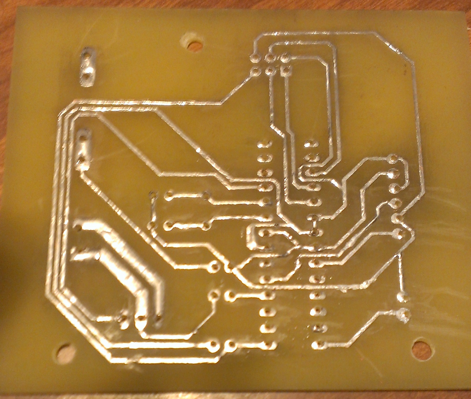
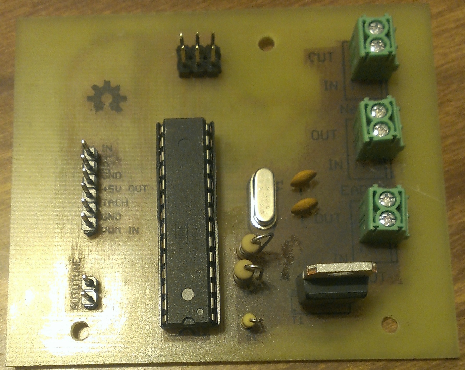
For anyone who is interested in controlling the speed of a universal AC/DC brushed motor (router, drill, etc), I'm working on a super simple and inexpensive controller design that can handle upwards of 25A loads. The exact build will vary depending on your current needs and input source, but total hardware cost is somewhere in the neighborhood of $10. It can be controlled either by a potentiometer or PWM output from a CNC controller. I am waiting for parts to build a prototype, but in the mean time, I've written some code in Arduino to run it. Code is below if anyone cares to review it. It currently uses the PID and Timer1 libraries, and I will be adding support for PID Autotune in the next revision. It's pretty short and simple code 
#include <TimerOne.h>
#include <PID_v1.h>

#define triacPin 5      // Output to Triac
#define inputPin A0     // Input from CNC controller
#define tachPin 3       // Input from Tach signal
#define zeroPin 2       // Input from Zero Cross Detector
#define FREQ 60 	// 60Hz power in these parts


double Setpoint, Input, Output;  //Define Variables we'll be connecting PID to
double wait = 3276700000;  //find the squareroot of this in your spare time please
PID myPID(&Input, &Output, &Setpoint,2,5,1, REVERSE);  //Specify the links and initial tuning parameters - PID takes RPM from tach as input, RPM from ADC0 as setpoint and gives phase delay time as output
int windowSize = 8333;  // AC half wave takes ~8333 microseconds
int tachMax = 29667;  // Maximum motor RPM
int inputScaler = tachMax/1023; //scalar value to convert analog input to RPM value for PID input
volatile long tachCount = 0;  // Counter for tach signal
volatile byte state = 255;  // controls what interrupt should be attached or detached while in the main loop
unsigned long int period = 1000000 / (2 * FREQ);  //The Timerone period in uS, 60Hz = 8333 uS
int inputWindow = 1000;  // time in milliseconds that ADC0 input is sampled and PID setpoint is adjusted (default 1000 = 1s)
double now, then, timeOld;  //timer variables for main loop
int inputTemp = 0;

void setup() {
  //initialize the variables we're linked to
  Setpoint = 0;

  // setup pins
  pinMode(triacPin, OUTPUT);
  digitalWrite(triacPin, LOW);
  pinMode(tachPin, INPUT_PULLUP);
  pinMode(zeroPin, INPUT);

  //set PID calculation frequency
  myPID.SetSampleTime(100);

  //tell the PID to range between 0 and the full window size
  myPID.SetOutputLimits(0, windowSize);

  //turn the PID on
  myPID.SetMode(AUTOMATIC);

  //setup timer for triac gate trigger
  Timer1.initialize(period);
  Timer1.disablePwm(9);
  Timer1.disablePwm(10);

  //Initialize timer variables
  timeOld = 0;
  then = 0;

  //setup ISR routines
  attachInterrupt(0,zeroCross, FALLING);  //IRQ0 is pin 2. Call zeroCrossingInterrupt on FALLING signal
  attachInterrupt(1,tachSense, FALLING);  //IRQ1 is pin 3. Call tachSense on FALLING signal

}

void loop() {
  now = millis();
  if(now-then >= inputWindow){
    Setpoint = analogRead(triacPin)*inputScaler;
    then = now;
  }
  if (tachCount >= 10){
    Input = (60000/(millis() - timeOld)) * tachCount;
    timeOld = millis();
    tachCount = 0;
    myPID.Compute();
  }
}


void zeroCross(){  //Zero cross detection ISR
  Timer1.restart();
  state=1;
  if (Output>=7915) {			//if Output is < 5%
    digitalWrite(triacPin, LOW);	//stay off all the time
    state=0;			// no update this period
  }
  else	//otherwise we want the motor at some middle setting
  {
    Timer1.attachInterrupt(nowIsTheTime,Output);
  }

}

void tachSense(){  //Tach input counter
  tachCount++;
}

void nowIsTheTime ()
{
  if (state=1) {
    Timer1.attachInterrupt(nowIsTheTime, (Output + 8333));
  }
  if (state>=1)		//the interrupt has been engaged and we are in the dwell time....
  {
    digitalWrite(triacPin,HIGH);
    wait = sqrt(wait);		//delay wont work in an interrupt.
    if (!wait)                      // this takes 80uS or so on a 16Mhz proc
    {
      wait = 3276700000;
    }
    digitalWrite(triacPin,LOW);
    state++;
    if (state==3){
      Timer1.detachInterrupt();
    }
  }
}
 Hmm, just thought of something I missed, be back with REV.3 shortly....